BRIEF: The brief for this assignment was to create a mudguard and connector, designed for a specific style of bike. The bike that me and my partner decided to use was an 12 speed road bike. The characteristics of the road bike meant that the mudguard would have cater for the thin wheels.
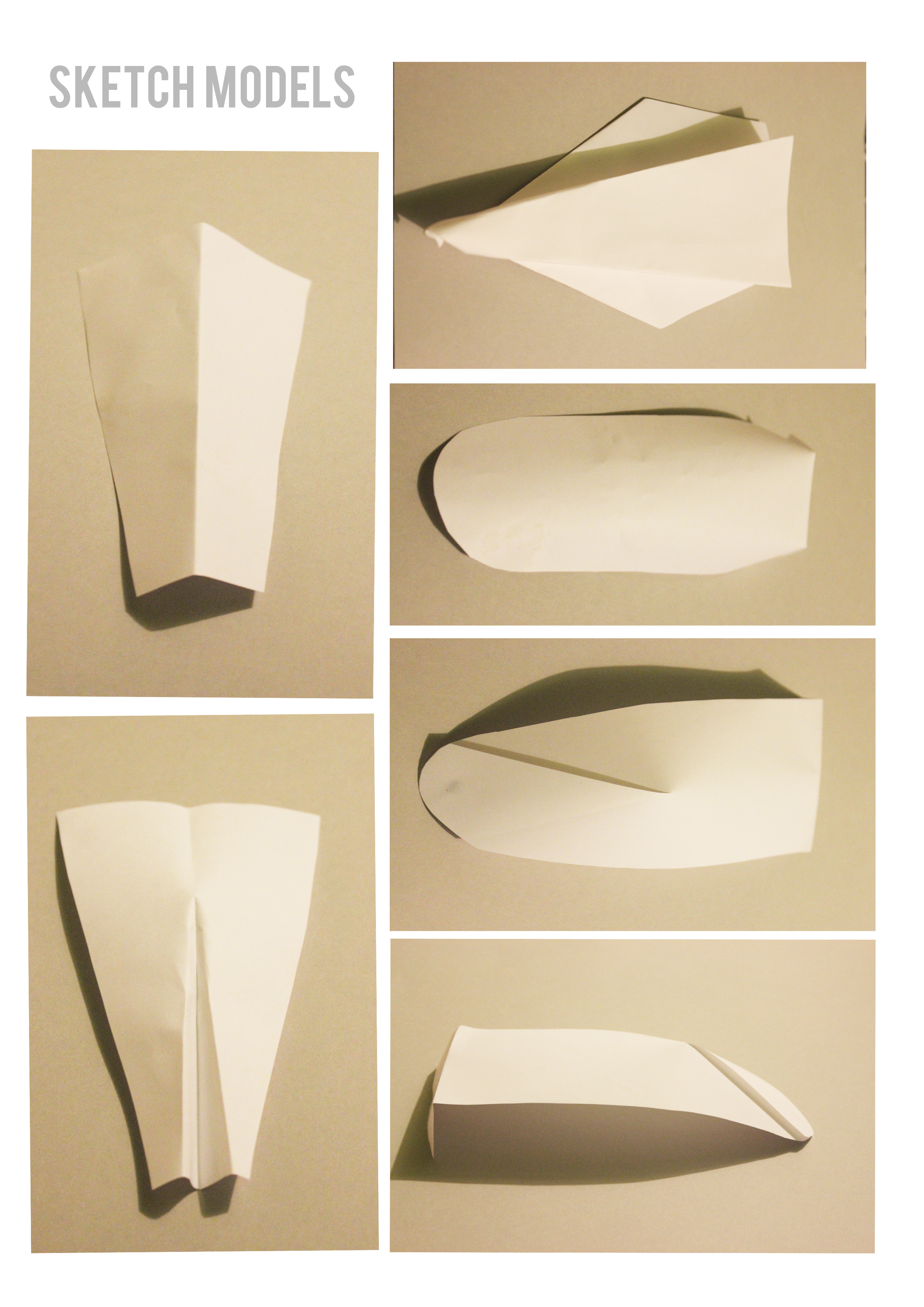
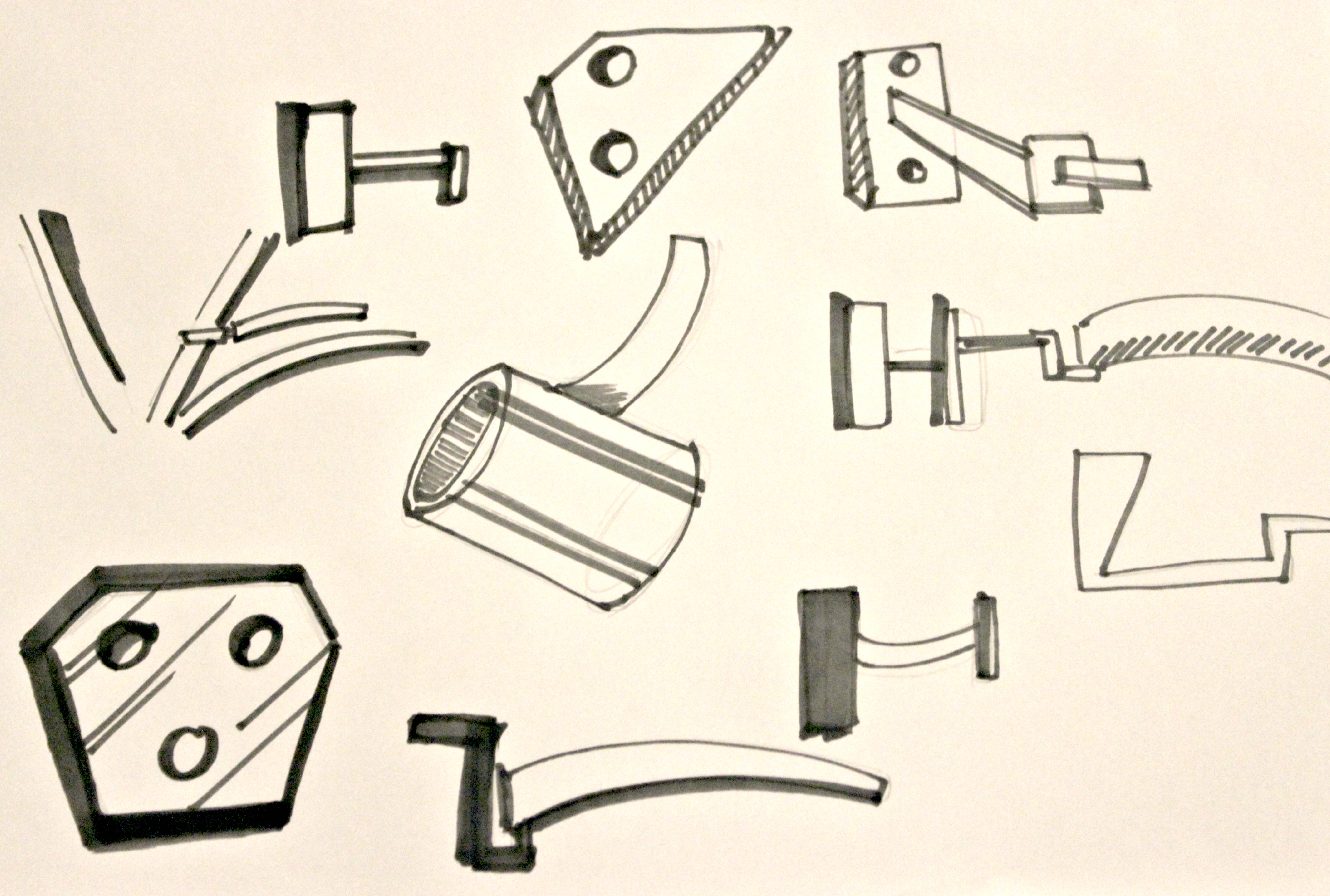
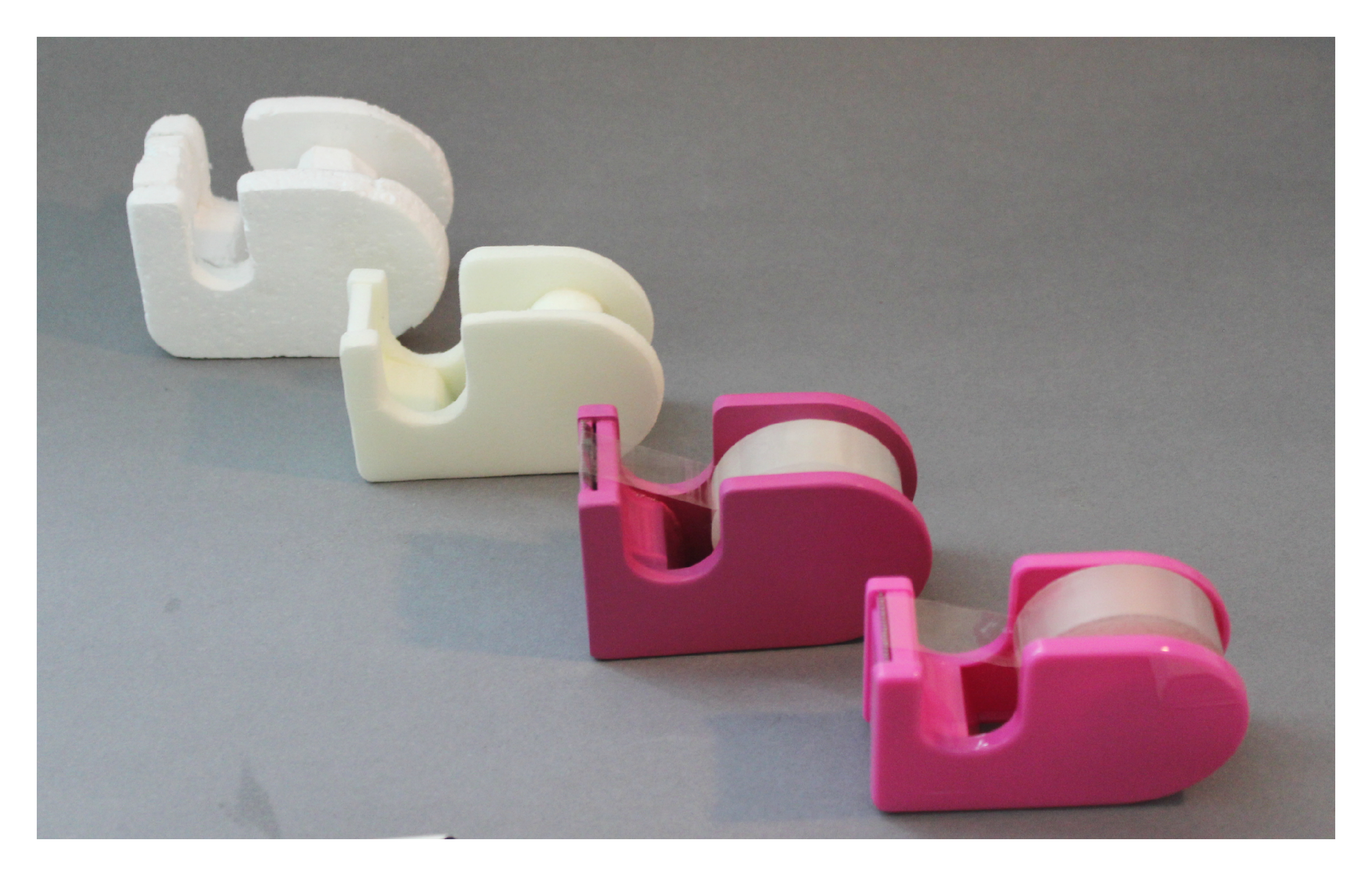
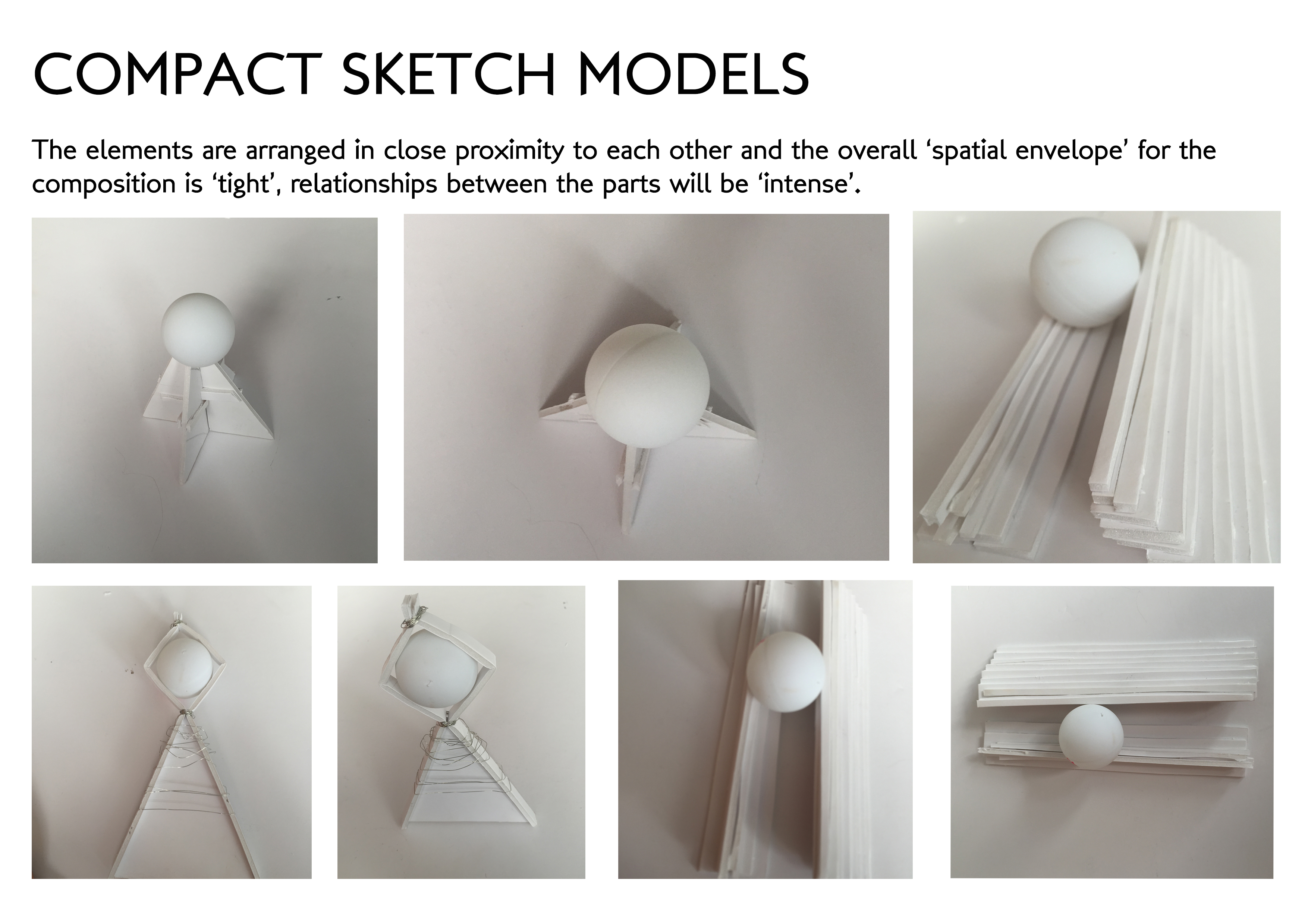
Chosen Bike: 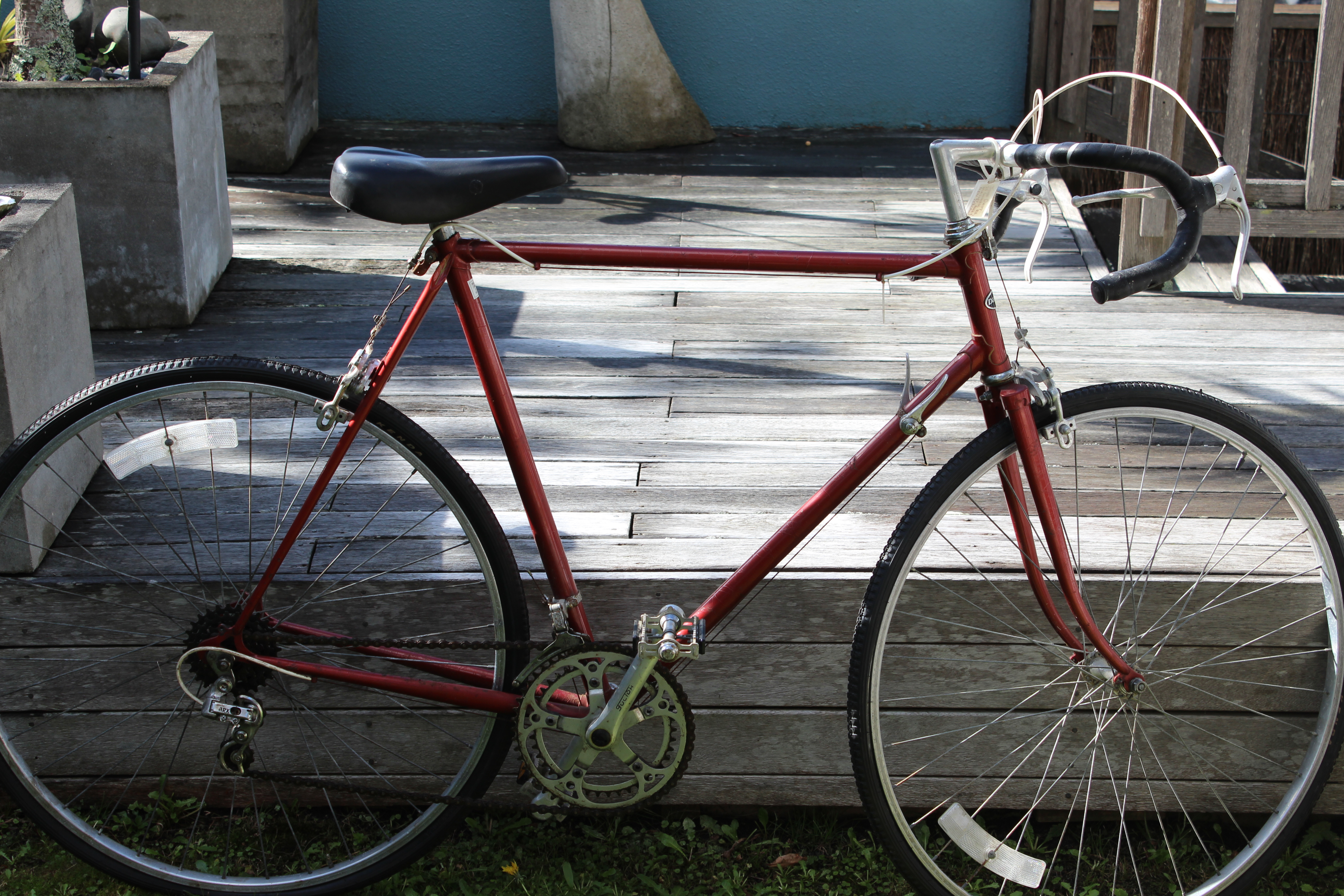 The first stages that I went through when thinking about mudguard designs was make sketch models. I experimented with different sizes and styles. This gave me a greater understanding of where I wanted the mudguard to be connected to the bike (front or back wheel) and the width of the mudguard itself.
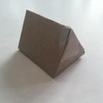
SKETCH MODELS: 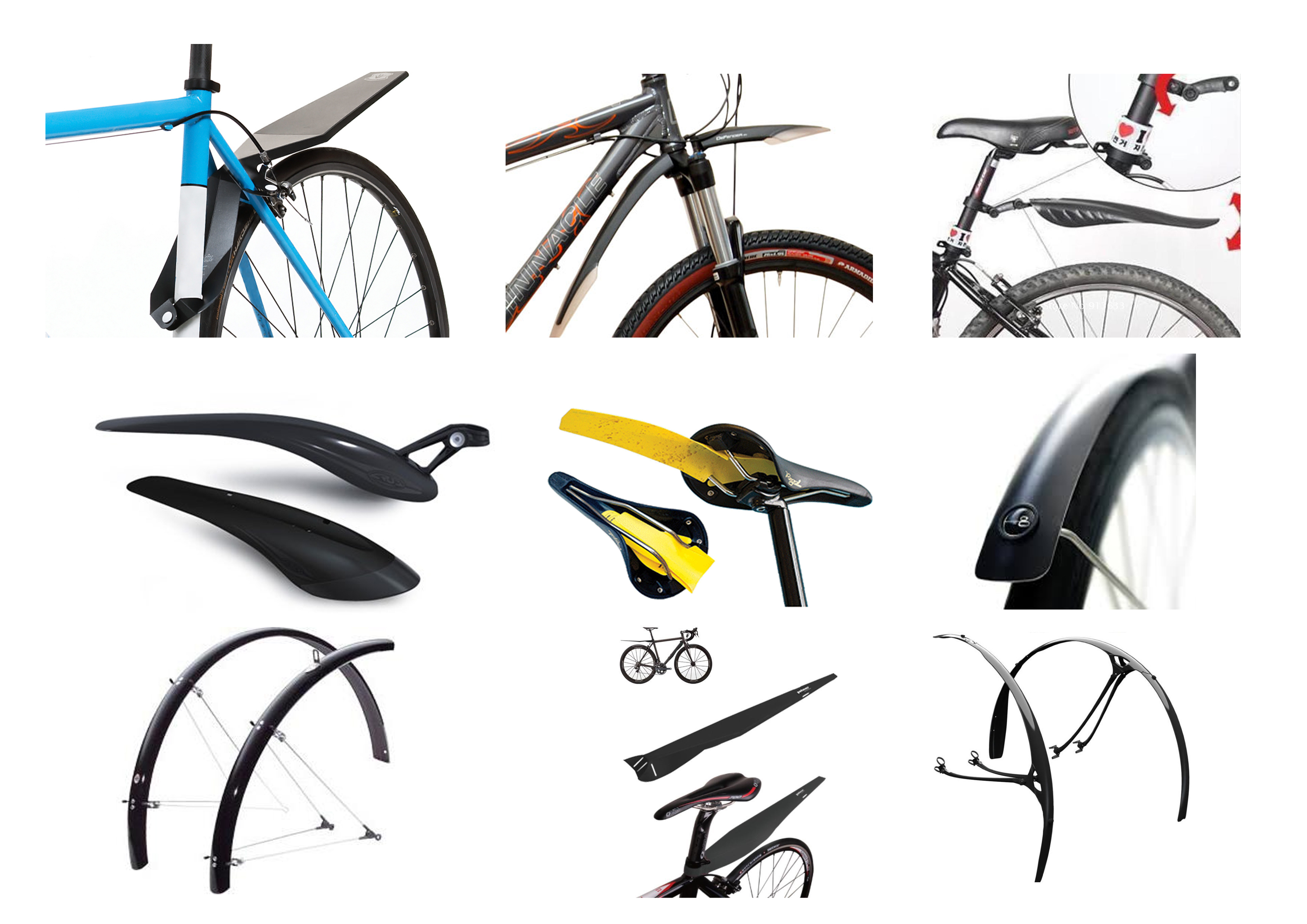

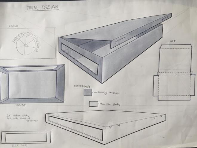
FINAL DESIGN:
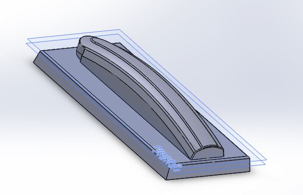
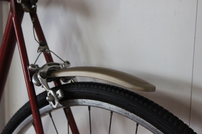
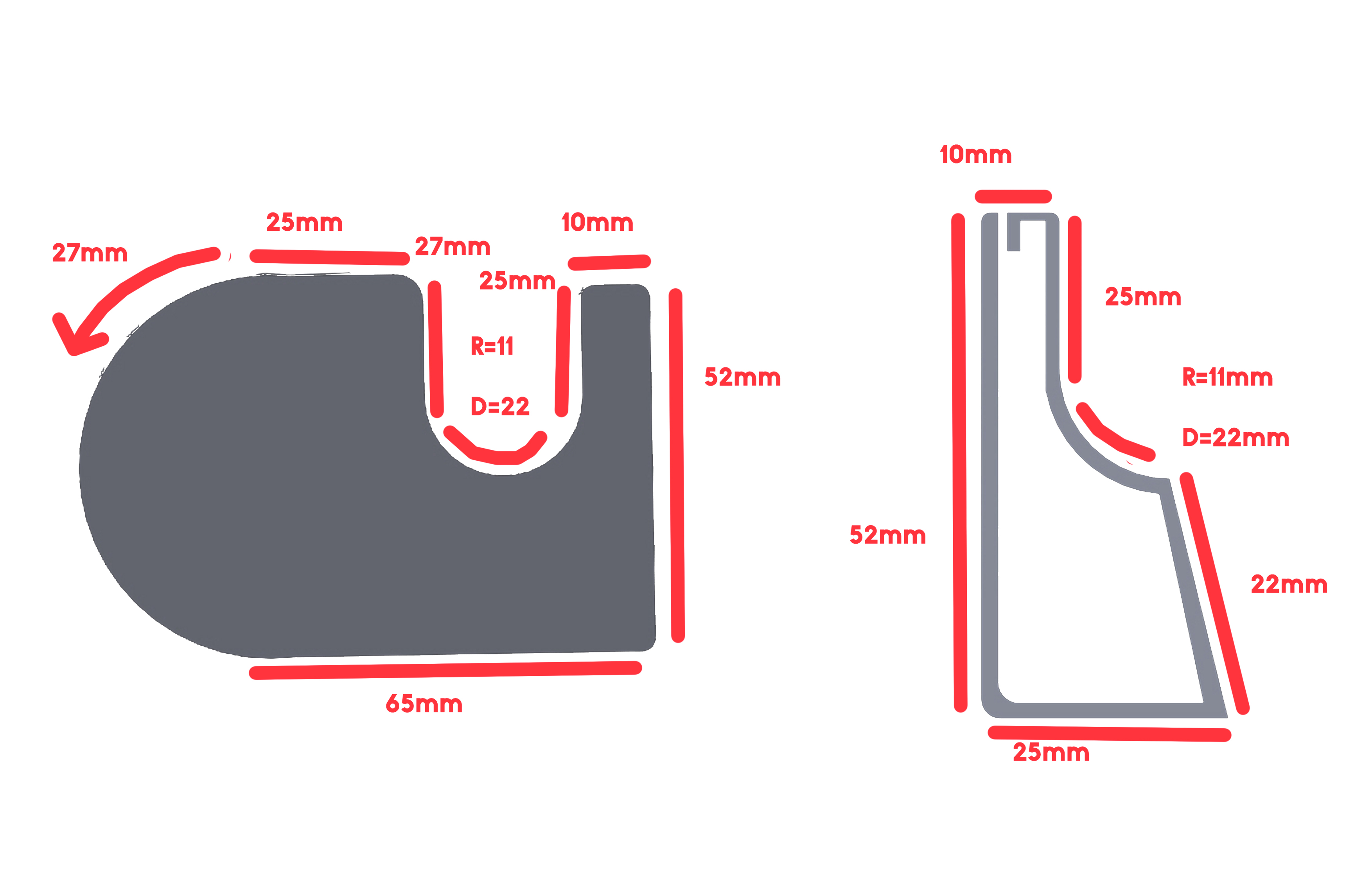
The final design that my partner and I came up with is a slender mudguard suitable for the back wheel of the bike. The mudguard is the perfect proportion to sit comfortably over the wheel and protect the rider from mud sprays. The style of the mudguard gives a cohesive link with the bike, because it gives of the same vintage style that the chosen bike has. The style of the mudguard has a rise going through the middle that tappers down to be flush with the rest of the guard. This relates to the repeated tapering features of the bike.


The rounded end of the guard has been taken from the style used on the bike to connected the metal sections to one another.
SOLID WORKS MUDGUARD FILE: 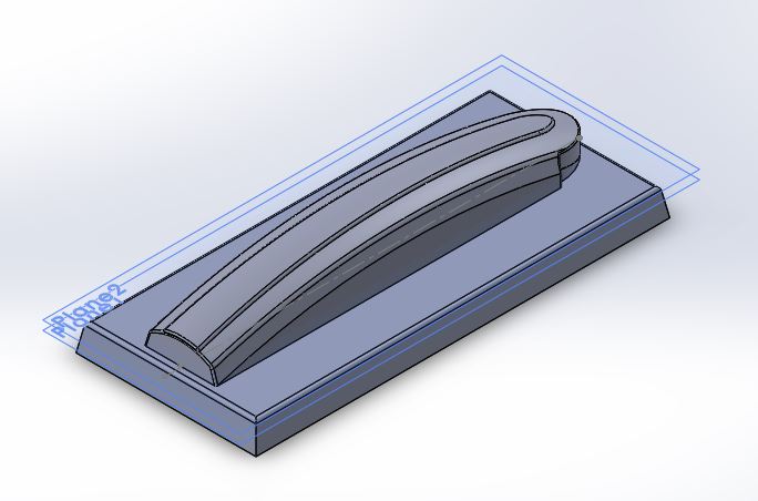

 The solid works file is then used with the CNC machine to produce a wooden mold to vacuum form the mudguard.
CNC: 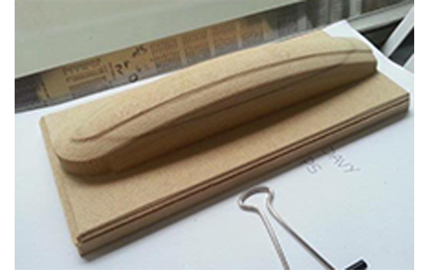
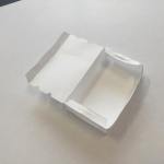
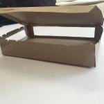
VACUUM FORMING:
To create the mudguard itself, you use the vacuum form machine. The machine heats the plastic, so it become malleable enough to stretch over and form the shape of the wooden mold. Before using the mold, it has to be sanded down with very fine sand paper and sealed. This is so the final design will have a smooth seamless finish. To test out the mold, I used 5mm thin plastic sheets. This gave me a clear idea of how pronounced the details would appear on the final outcome, and how the vacuum former works.
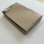
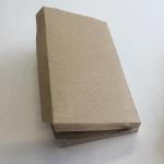
TEST MODEL:  I sanded the surface of the plastic with 600grit sandpaper to see if it would be smooth enough for spray paint. I also practiced drilling through the plastic. I knew that I would need to know this for my final model. I was very happy with the outcome of the test model, and ready to mold my final.
CREATION:
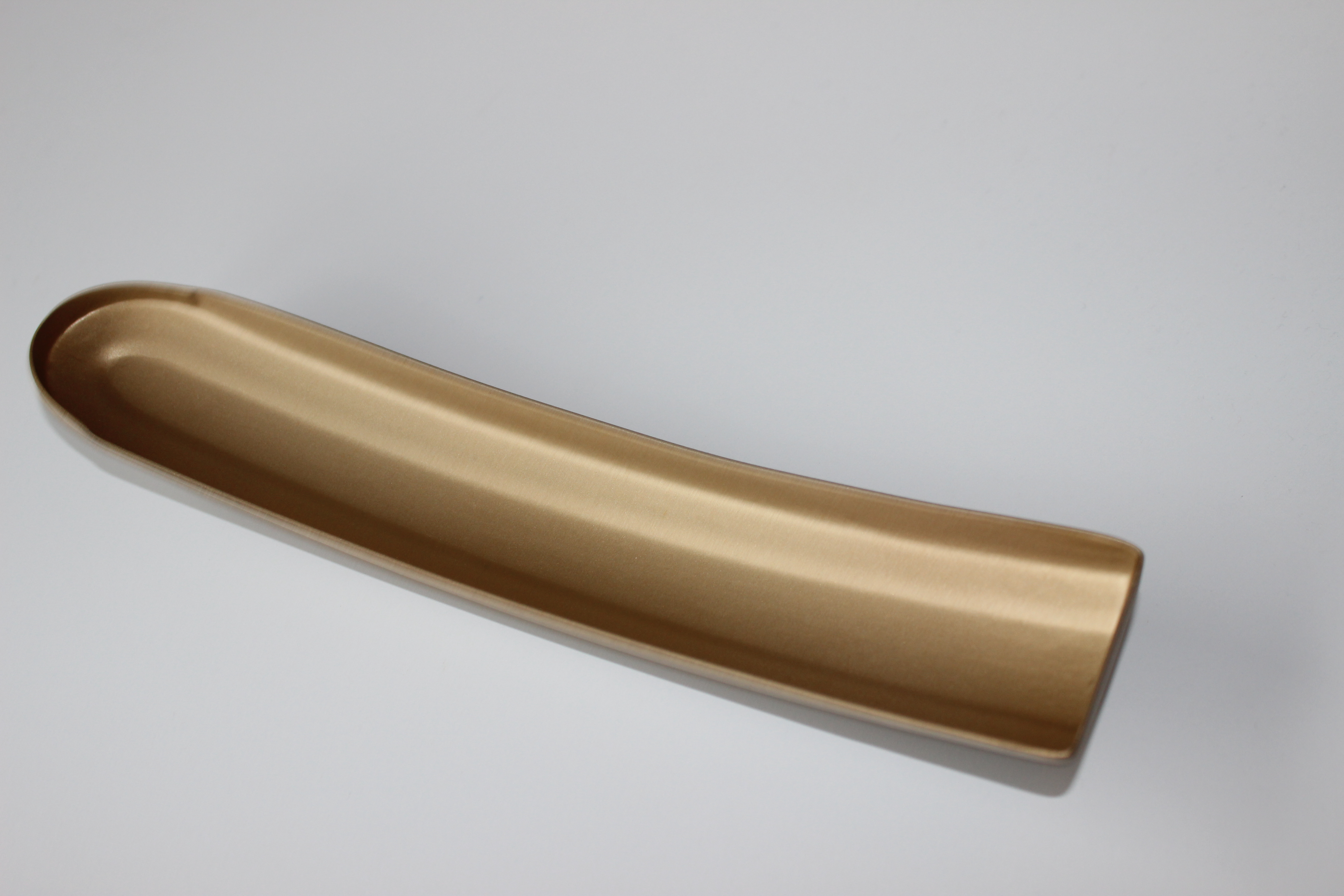
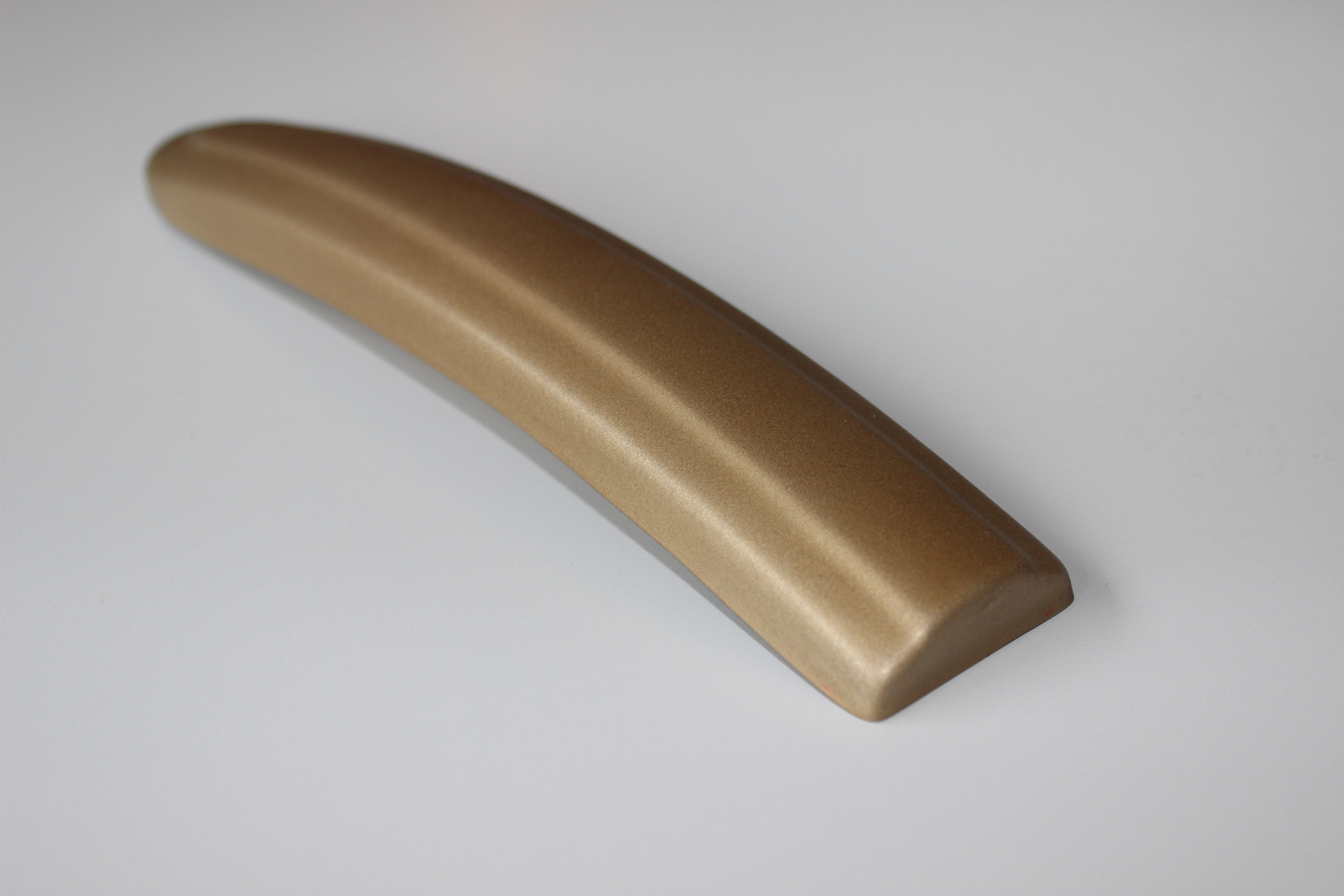
For the molding of my final guard, I used PETG UV clear plastic, 1.5mm thick. I set the timer of the vacuum form machine to 34 seconds. The outcome of my first mold wasn’t as crisp as I wanted it to be. It wasn’t tight to the mold around the edges. The second time I molded it, I put it on for 58 seconds. The outcome was much tighter and had a nicer form. I used a dremel saw to cut the guard out. I drew an even line around the edge to where I wanted to sand up to. 
I sanded down the surface of the mudguard with 600grit to give an even surface. I purchased a gold spray paint from Car colours as well as a satin top coat to give it a long lasting shining finish. I chose a gold colour to paint the mudguard, because this was the same colour used for the bikes detailing.
 It gave a subtle link from the bike to the guard, without letting it blend in to much with the bike.

MUDGUARD CONNECTOR:
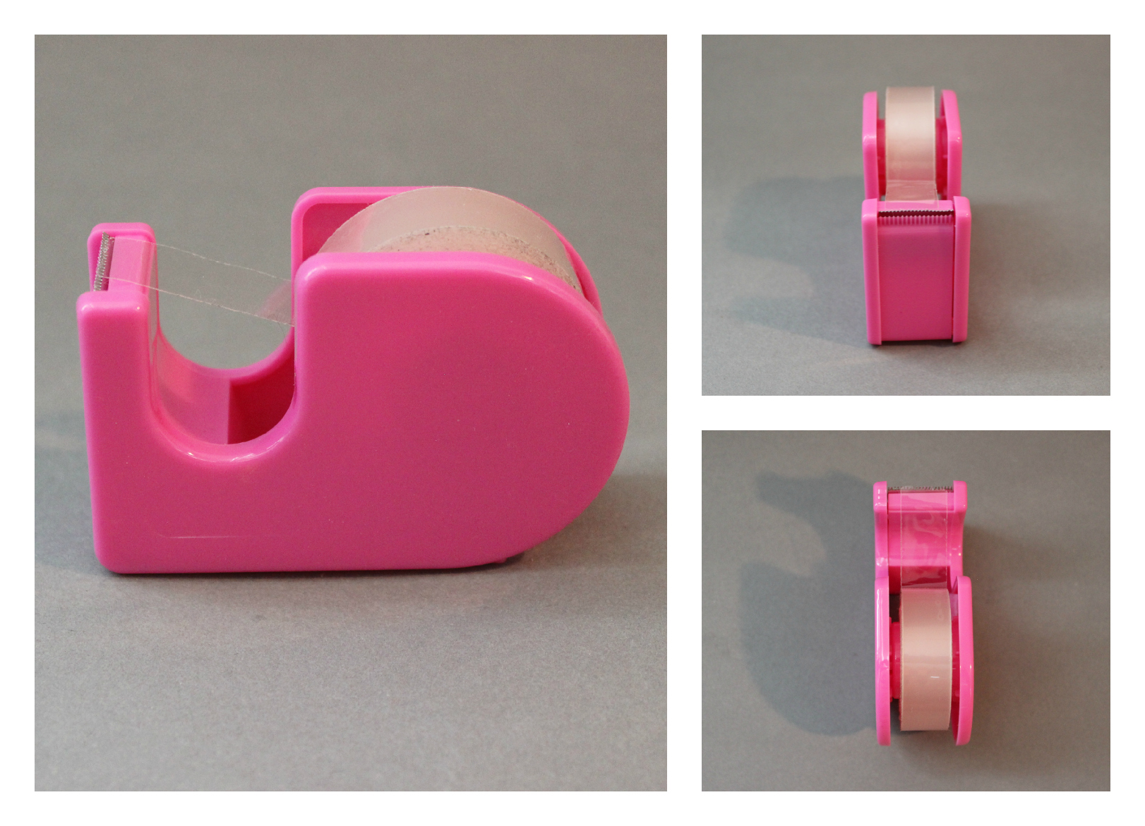
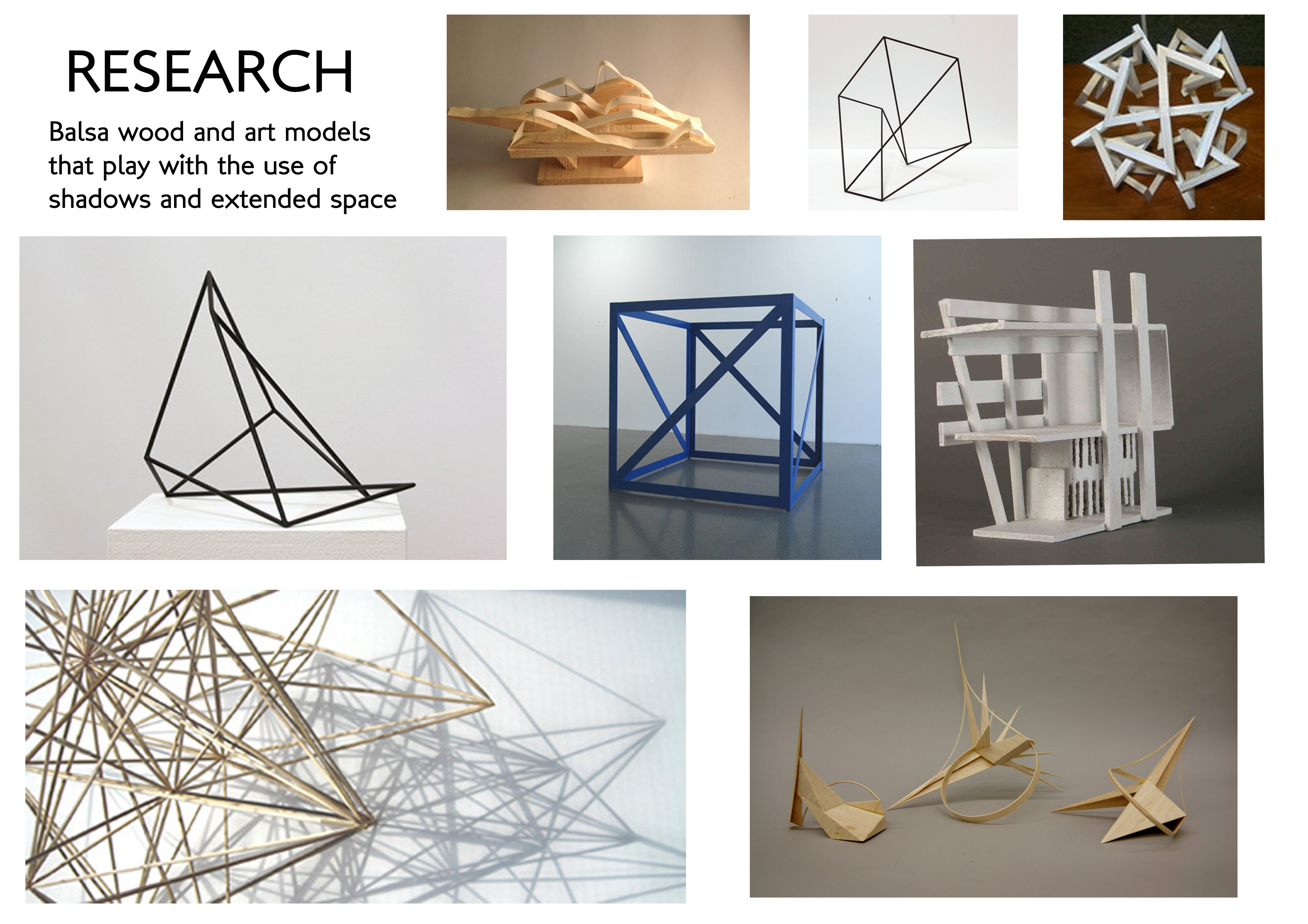
When creating my mudguard connector, I started by doing research. I looked at already excising mudguards and began doing some quick sketches.
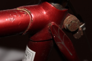
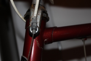
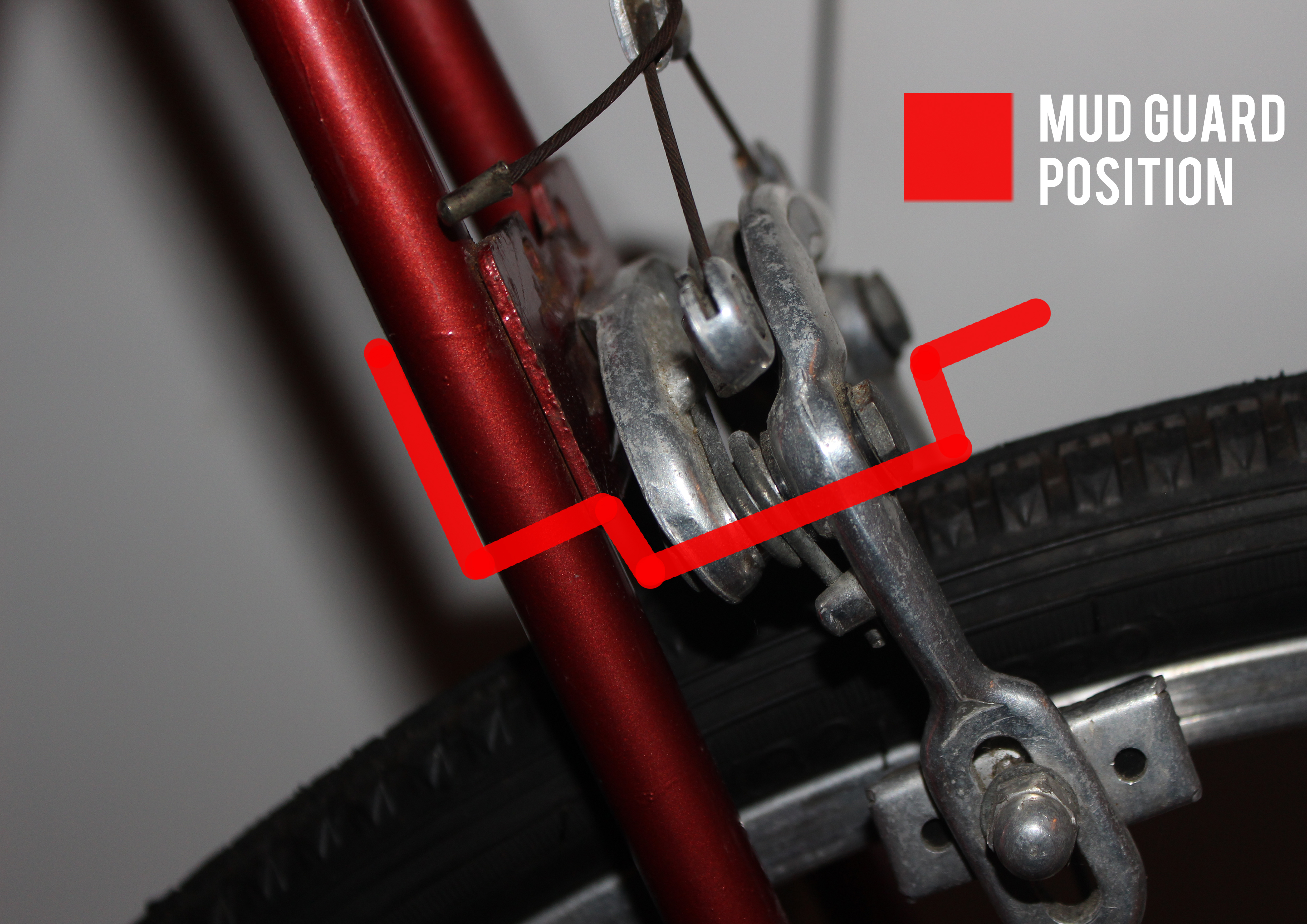
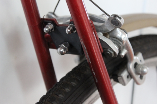
MUD GUARD POSITION:
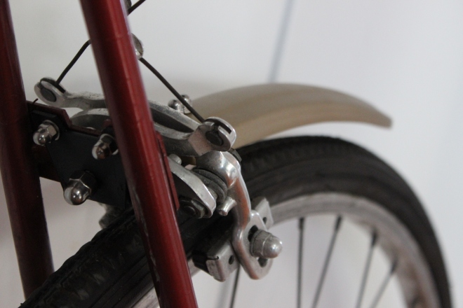
The mudguard connector will sit around the brake system.
FINAL DESIGN:
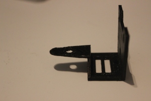
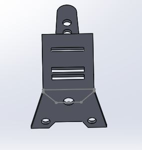
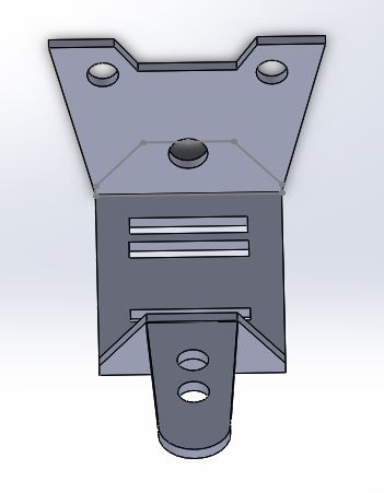
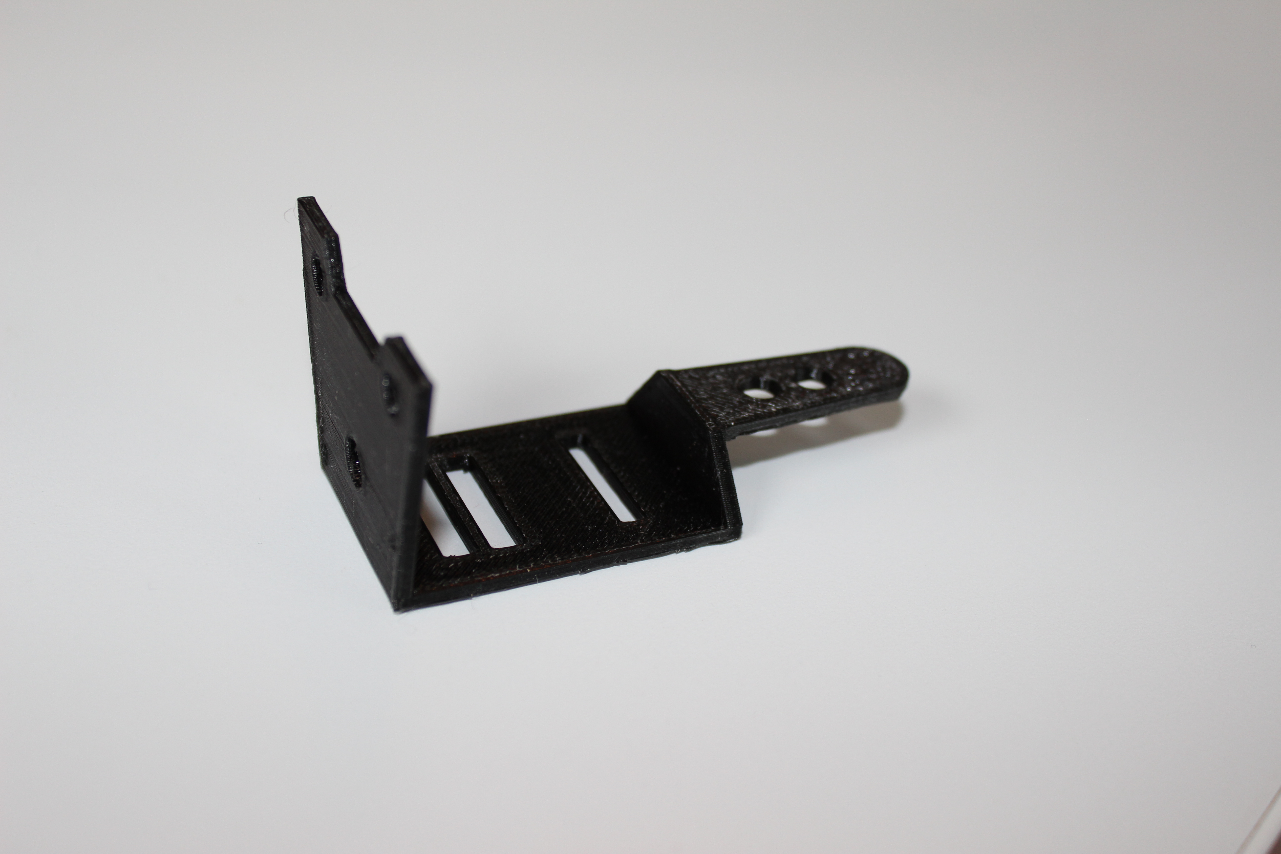
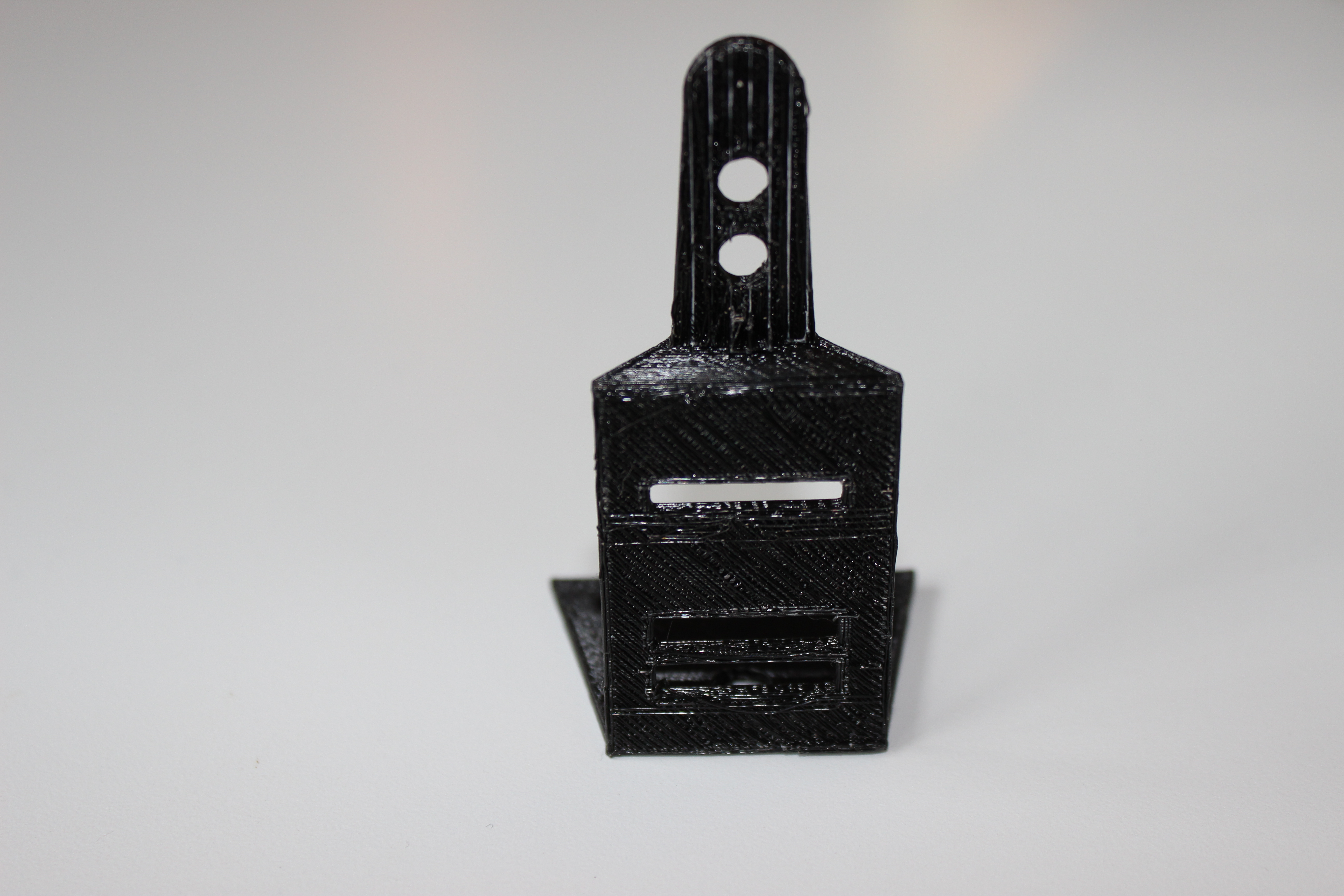
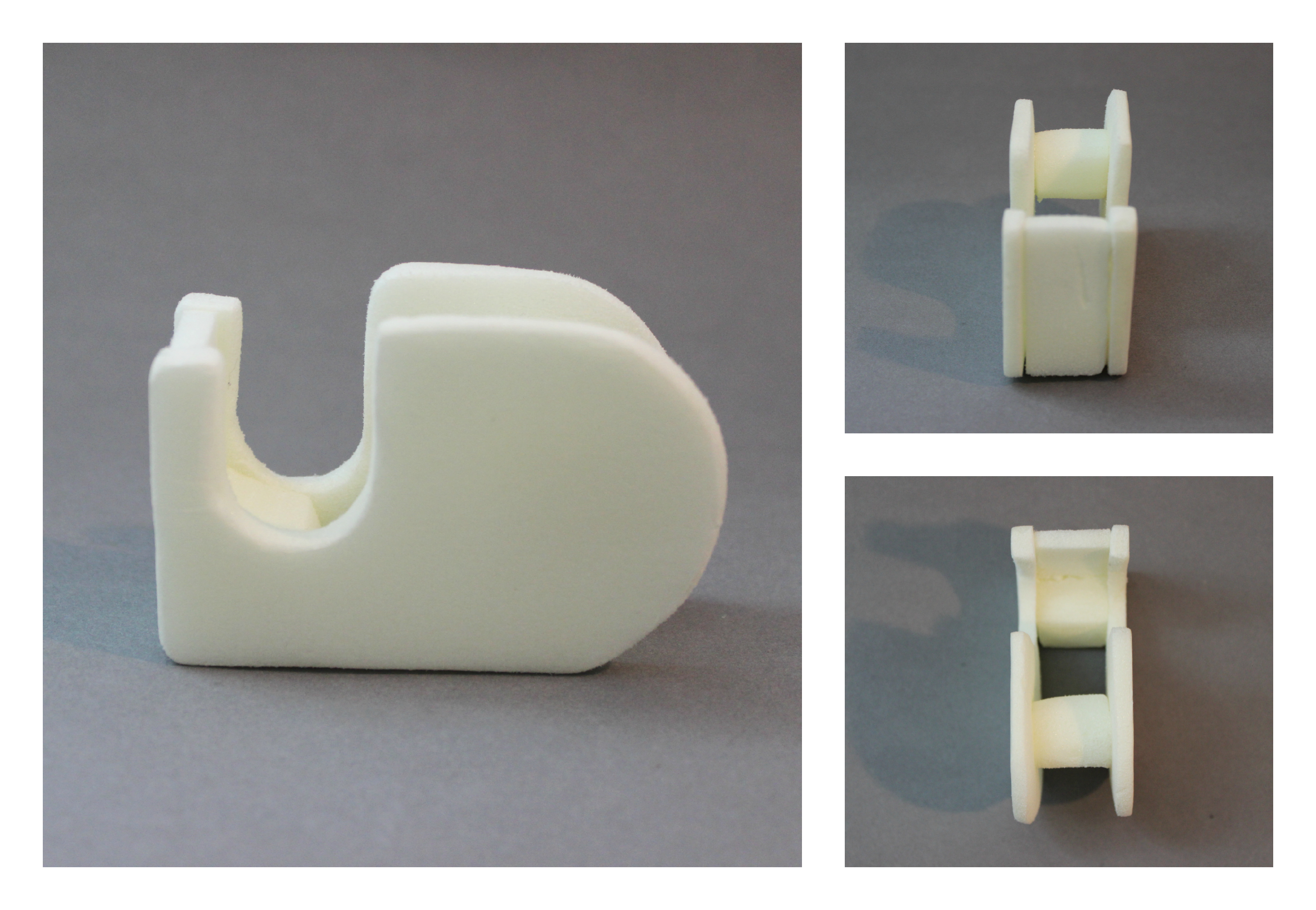
For my final design, I came up with a unique design that fits perfectly onto my chosen bike. Because I was creating a design for the back wheel, I had to make sure that it was able to fit around the old fashion break system. The flat section fits securely onto the bike which will be attached with bolts. The connector sits comfortable under the mudguard itself, which will also be attached with bolts. The design is black which adds the the subtle style of the design. The connector doesn’t look obtrusive among the bike and doesn’t take away from the guard. 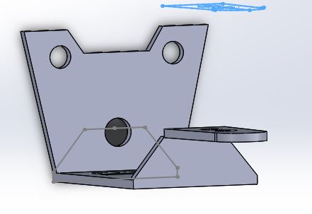 Printed connector:
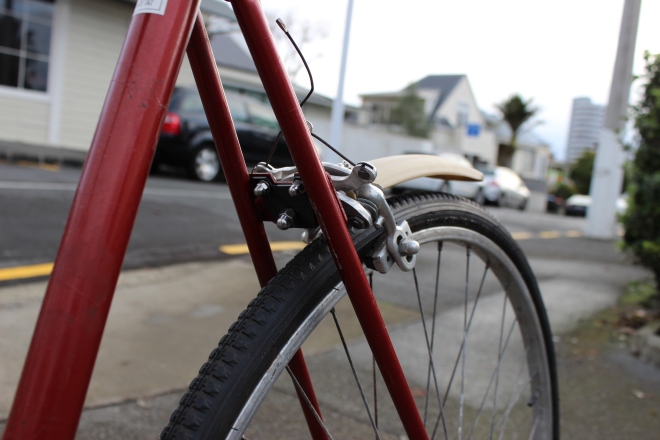
After getting my first connector printed, I realised that the middle section was to short. The connector was unable to fit around the brake. The other sections of the part, (flat section and end) fit perfectly onto the bike and connector. I went back to solid works and made the middle section 1.5cm longer. This would hopefully give a comfortable fit around the brake.
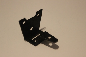
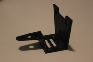
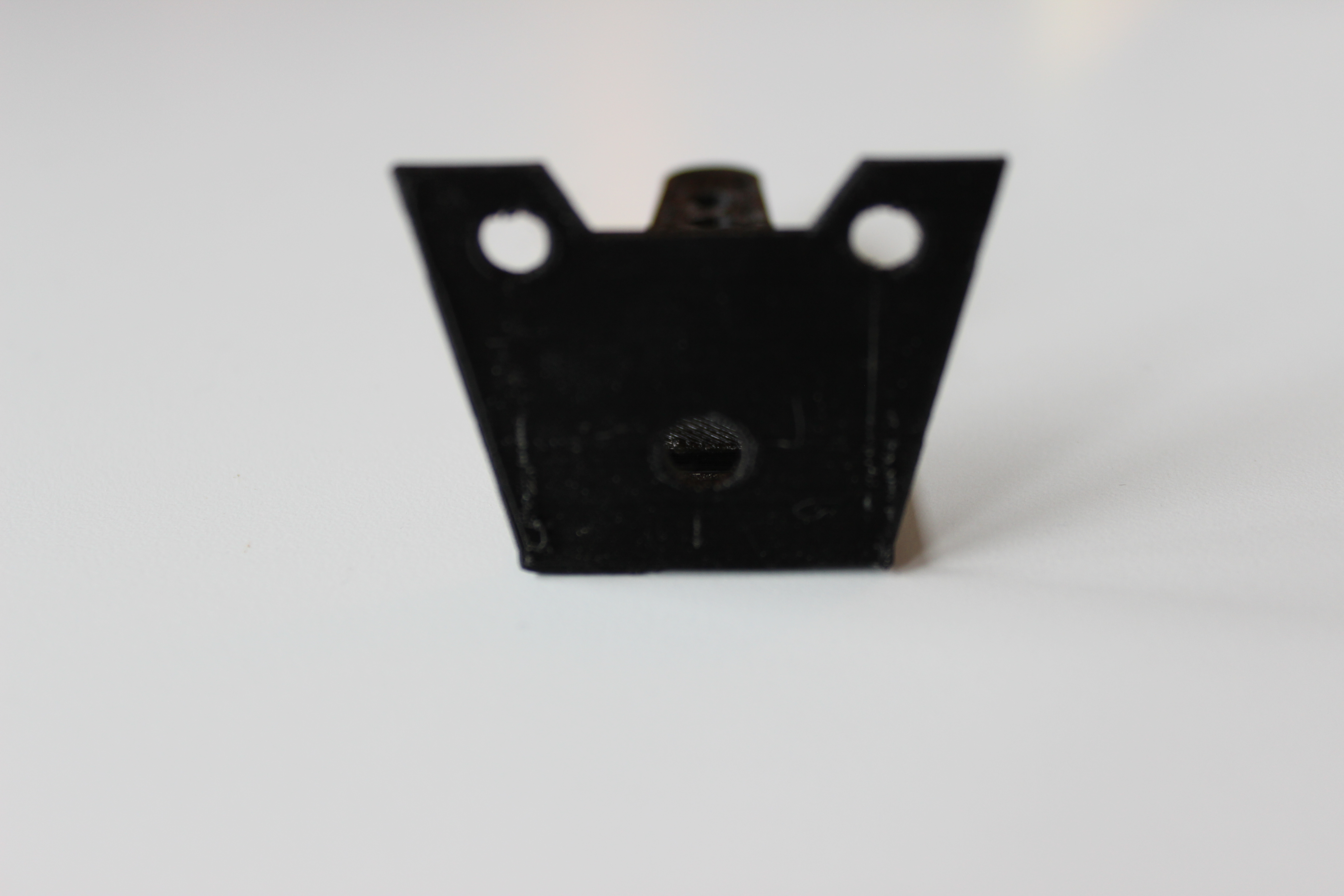
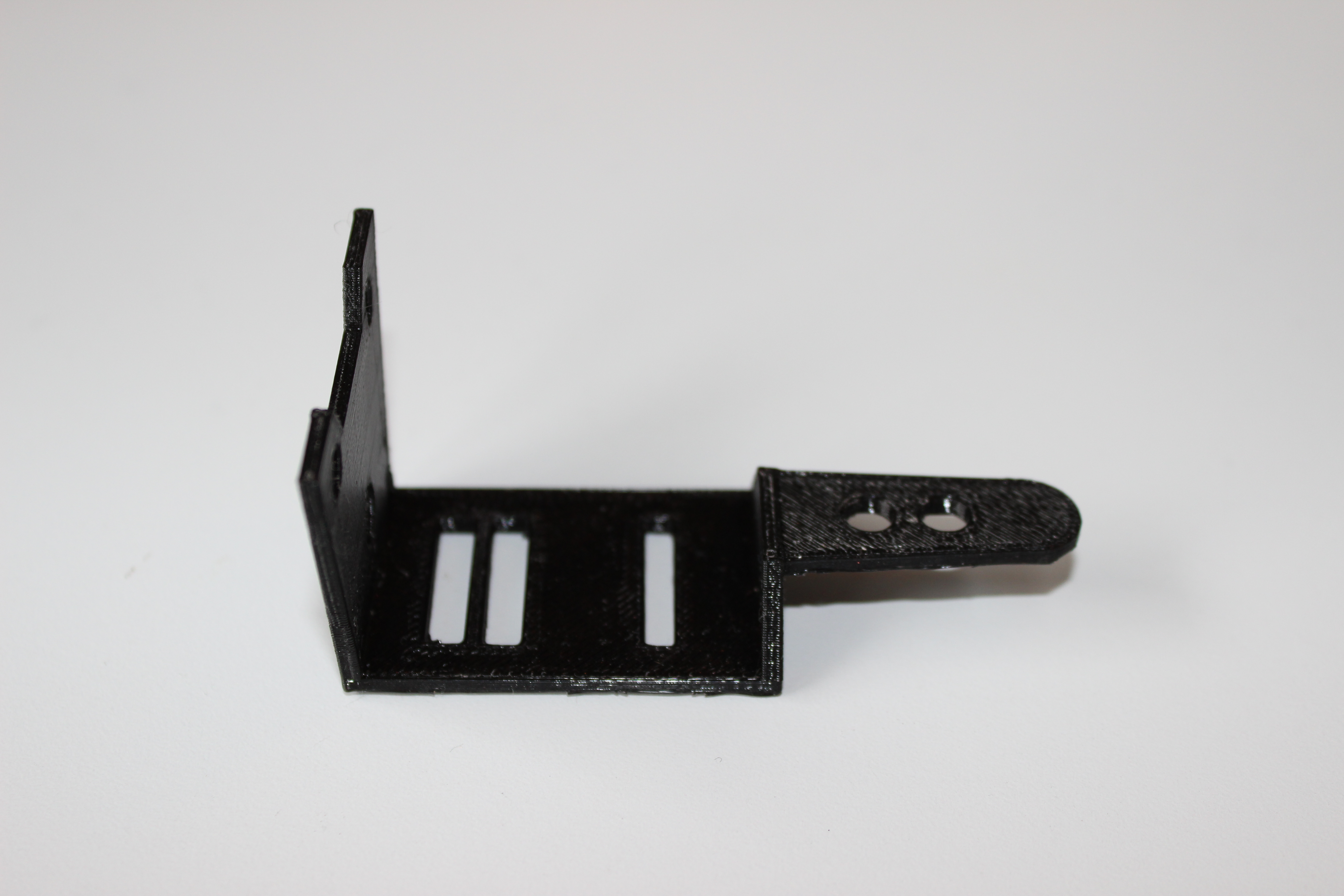
Second Printed connector:

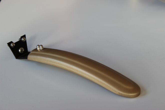
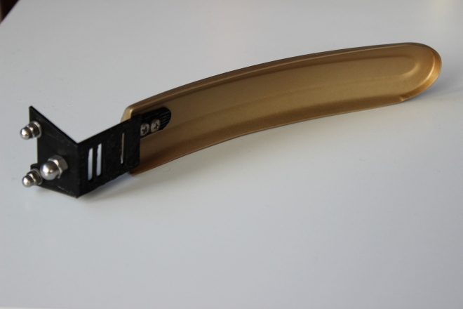
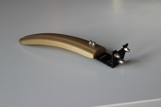
The second connector fit perfectly on the bike.
Printed:
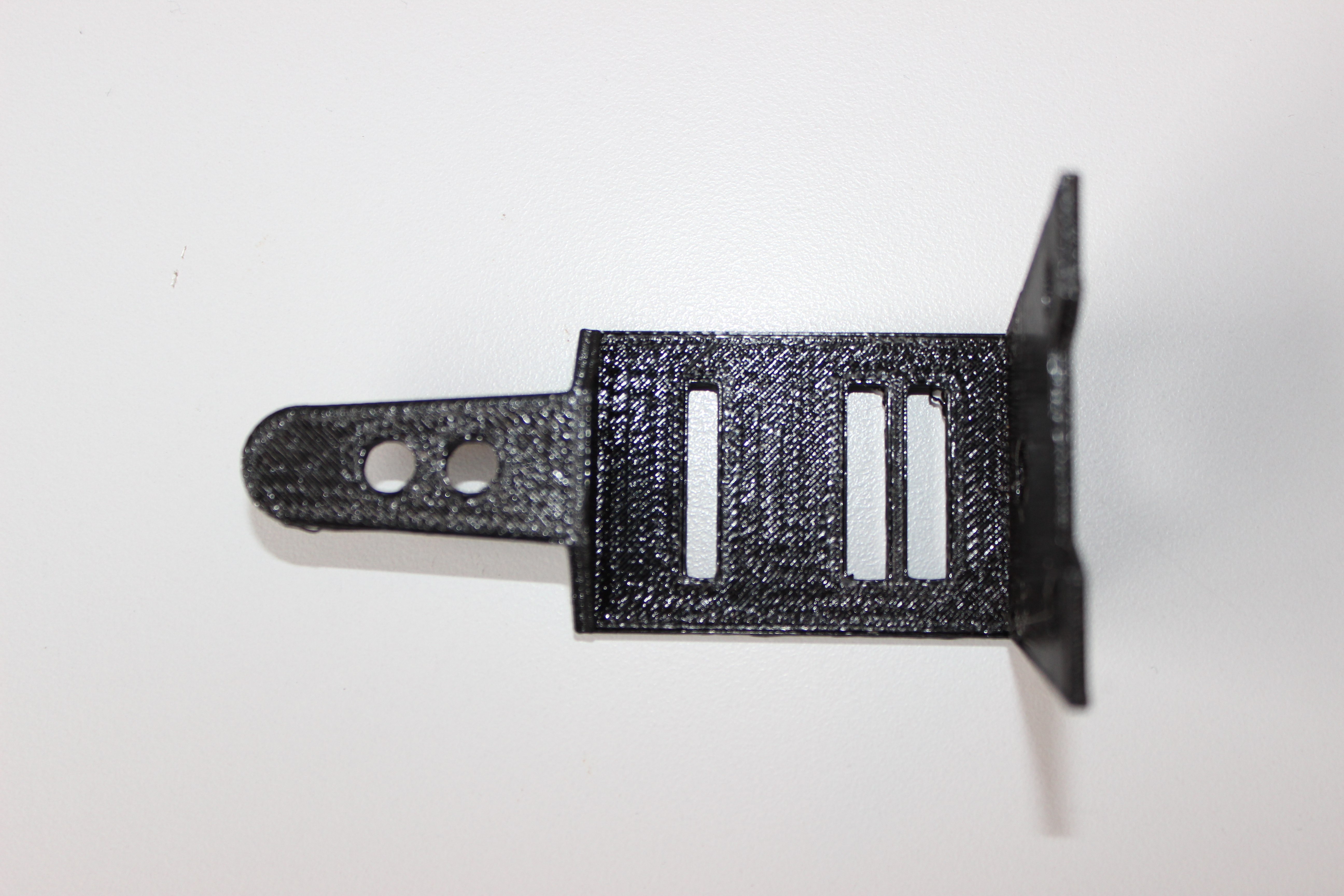

I purchased dome headed bolts from ‘Anzor’ to give a polished feel to the final outcome.
FINAL DESIGN:


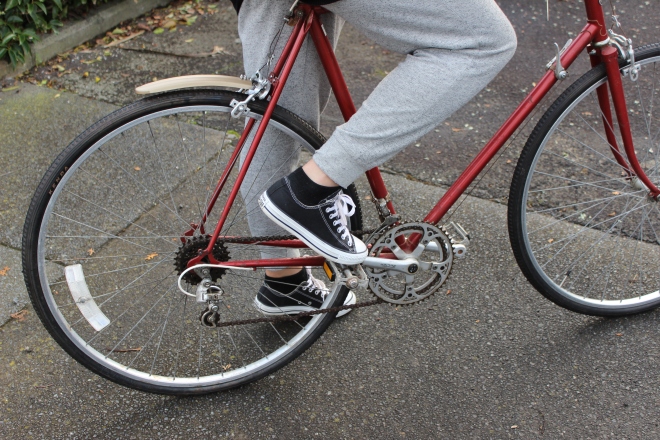

BEFORE AND AFTER MUDGUARD:
Presentation Boards:


![IMG_7902[1]](https://mollydavy.wordpress.com/wp-content/uploads/2015/03/img_79021.jpg)